Troubleshooting Manual
Warning! According to the GB law gas boilers are falling under ‘controlled service’ appliance. Only qualified personnel (GasSafe registered technician)can perform service, installation and repair works on Main Boilers. Also note that any work performed on the Main appliance without written permission from the manufacturer or his agent could invalidate the warranty appliance.
In an Emergency
When you suspect water or gas leak turn off the electrical supply and turn gas supply at the meter immediately. Open the windows to let the fresh air and call your customer support immediately and request service boiler technician as soon as possible.
Before using the boiler for the first time, after reapir or/and restart following checks should be done
- that gas is available at the boiler. minimum gas pressure is 36mbar (propane), 19.5mbar (natural gas), 27mbar (butane)
- that water is available at the boiler (pressurised to 0.5 bar), if the system pressure is set at the right levels, where not refill, vent and re-check the system
- electrical supply (230V ~50 Hz.CH ) is available at the boiler
- check correct electrical polarity, earth resistance
- test and earth continuity and test short circuit
- start boiler to verify correct operation of its control system
- examine all ventilation openings, those need to be right size and its opening needs to be clear
- whenever one of the components was exchanged Move the the selector switch anti-clockwise till you reach the reset position and hold for at least 5 seconds to reset the boiler.
- Attention! Before any servicing or replacement of parts ensure the gas and electrical supplies are isolated.
Boiler operation
The boiler is capable of operating in two modes: central heating and domestic hot water. Mode is controlled the selector switch on the facia panel. When set to Central Heating mode it will operate in both domestic hot and central heating mode with the domestic hot water mode overtaking central heating mode whenever demand occurs. When set to Domestic Hot Water it will operate only in this mode, central heating won’t be provided.
Central Heating Mode
For the heating demand, the pump needs to circulate water through the primary circuit. Central flow switch operates at the pre-determined rate and it starts the ignition sequence. The main burner will always ignite at low rate, then the gas valve control the gas rate in order to keep the heating temperature measured (by the temperature sensor). A 3 minute delay  will occur before the burner relights automatically (anti-cycling) in all instances where the temperature flow exceeds the setting temperature. The pump continues to run during this period. C.H. Flow Temperature (adjustable) 35°C to 85°C max (± 5°C). Following pressures should be sustained for optimal operation:
- Safety Discharge 3Â bar
- Max Operating 2.5Â bar
- Min Operating 0.5Â bar
- Recommend Operating 1-2Â bar
Domestic Hot Water ModeÂ
Priority always is given to the domestic hot water supply. A demand at a tap or shower  is the primary demand and because of it it will override the central heating requirement at the particular moment. The water flow will operate the DHW flow switch which causes the 3 way valve to change position. This will allow the pump to circulate the primary water through the DHW plate heat exchanger. The burner will light automatically and the temperature of the domestic hot water is controlled by the temperature sensor. Unless there is a demand for central heating  the domestic hot water demand will cause burner extinguish. The diverter valve will remain in the domestic hot water mode. D.H.W. Flow Temp (adjustable) 35°C to 65°C max (± 5°C) dependent upon flow rate. Following pressures should be sustained for optimal operation:
- Max Operating 8Â bar
- Min Operating 0.2Â bar
- Min Operating Pressure at 9.8 l/min 0.9 bar
Attention: When selector switch is in the off position then the electrical power supply to the boiler is also isolated. Your appliance won’t work and the integral timer (when fitted) will have to be resetted each time the sector switch is tuned to either DHW or CH position
Fault finding
Before starting troubleshooting your appliance make sure that all checks listed above were carried out (electricity, polarity, gas, ground continuity, circuit etc) and then isolate the gas and electrical supplies.
Table A. Â General Main System HE Range fault finding table
| Problem | Cause/Solution |
|
Boiler is not working
|
Verify that the gas supply is ON, you can easily verify if other gas appliances are working (e.g. cooker). If no gas contact your gas supplier |
| Is the ON/OFF/Reset Select Switch in the ON position and the Power ON indicator lit? Check the electrical supply. If no electricity supply contact your electricity supplier | |
| Turn the Reset Selector Switch/OFF/ON to Reset | |
| If problem persists contact your installer or gas boiler specialist | |
|
No central heating
|
Is the Timer ON and calling for heat ? Ensure timer is set for Central Heating ON (see any instructions supplied with timer). |
| Verify if the Room Thermostat (if fitted) set high enough. Turn Room Thermostat to maximum setting | |
| If problem persists contact your installer or gas boiler specialist | |
| Is the Central Heating System Pressure needle in the GREEN section, between 1 and 2.5 bar if not re-pressurize the system | |
| Air Flow Monitor neon illuminating | Air Flow Monitor indicates that the flue or flue terminal is blocked or obstructed in some way, or that there is an internal fault. If there is no external blockage of the flue terminal that can be easily removed contact your installer or boiler specialist |
| Pump Fault neon illuminating | Check the pressure gauge. If the pressure is in the normal range, a pump fault is indicated. Contact your Installer or boiler specialist to determine the fault. |
| Sensor neon illuminating | When sensor neon is illuminated a fault on one of the temperature sensors is indicated. Replace the temperature sensor and contact your installer or boiler specialist |
| Safety Thermostat neon illuminating | Reset your appliance: switch the selector to the ‘Reset’ position for at least five seconds then release. If after turning the selector to the Reset’ position the boiler does not relight or the safety thermostat operates repeatedly, causing boiler shutdown, contact contact your installer or boiler specialist |
Table B. Â General Main Combi 24Â fault finding table
| Problem | Cause/Solution |
|
Boiler is not working
|
Verify that the gas supply is ON, you can easily verify if other gas appliances are working (e.g. cooker). If no gas contact your gas supplier |
| Is the ON/OFF/Reset Select Switch in the ON position and the Power ON indicator lit? Check the electrical supply. If no electricity supply contact your electricity supplier | |
| Turn the Selector Switch/OFF/ON to Reset | |
| If problem persists contact your installer or gas boiler specialist | |
|
No domestic water
|
Is the hot water neon ON ? Ensure that the timer is set for Domestic hot water is ON . |
| Is mains water filter and differential assembly clean? If yes Replace DHW flow microswitch | |
| Continuity across DHW flow microswitch terminals and PCB – M1 connector terminals 13 & 14 (terminals 12-14 open), replace PCB | |
| If problem persists contact your installer or gas boiler specialist | |
| Pump Fault neon illuminating | Check the pressure gauge. If the pressure is in the normal range, a pump fault is indicated. Replace pump.Contact your installer or boiler specialist. |
| Primary flow switch not operating | CH system pressure 0.5 to 1.5 bar if not re-pressurize system. Check the tap of the automatic air vent is opened, if not open it. |
| Fan runs at max speed | Has safety thermostat been activated? If yes, Turn selector to reset position. If regular resetting is required, or appliance still does not operate contact your installer or boiler specialist Overheat thermostat operated or faulty, i.e. continuity across thermostat terminals if yes replace safety thermostat |
| Burner output doesn’t modulate until set temperature is reached | Check the burner setting pressure of the gas valve. Replace gas valve or/and replace PCB |
| Sensor neon illuminating | When sensor neon is illuminated a fault on one of the temperature sensors is indicated. Replace the temperature sensor and contact your installer or boiler specialist |
| DHW flow valve senses no flow. Primary water diverted to CH system. DHW flow switch released off | Diverter valve spindle assembly faulty. Replace. If problem persists contact your installer or gas boiler specialist |
Table C. Â Main Combi Eco Elite fault finding based on error codes table
| Problem | Cause/Solution |
| Error 20, 28 or 50 illuminating | E20 or E50 – Temperature sensors faulty E28 – Incorrect PCB fitted. Replace sensor or PCB (E28) |
| Error 110 illuminating | Overheat thermostat operated or faulty, i.e. continuity across thermostat terminals. Of no then replace safety thermostat and replace PCB |
| Error 119 illuminating | Primary water pressure is less than 0.5 bar. Re-pressurize the system |
| Error 130 illuminating | Overheat thermostat operated or faulty, i.e. continuity across thermostat terminals. Of no then replace safety thermostat and replace PCB |
| Error 133 illuminating | Interruption Of Gas Supply or Flame Failure, faulty overheat thermostat- replace |
| Error 160 illuminating | Fan connections not correct at fan. PCB – X2 connector, is 230V AC across terminals 5 & 7 not correct. Replace fan, replace PCB |
Appliance annual service
For economy and safety reasons your appliance should be serviced yearly. Boiler specialist will inspect and clean or/and replace all needed parts. Annual service takes around 2 hours and can be done during non heating period. Except boiler’s proper operation boiler specialist will verify proper ventilation. Remember to never hang flammable items over the boiler or/and never block ventilation channels. The boiler does not require any special air vents for cooling purposes when installed in a cupboard or compartment. but minimum clearances should be kept for optimal servicing purposes.
All Main boilers models aren’t suitable for external installation. The appliances should be installed on the vertical wall that supports the weight of your appliance (20-80 kg depending on a model). The main boilers can be installed in any room or internal space if IEE Wiring Regulations are followed.
 Parts replacement
Warning! Before start to work on any Main boiler model set the boiler into OFF position ,close valve that supplies fuel and isolate the supply of electricity. Wait till the boiler cools down and pay special attention to:
- always have a first-aid treatment near the place you work
- avoid inhaling any gas related vapours or direct contact with gas with skin, work in a room with open window
- avoiding any skin contact with hot/boiling water or/and with clothes contaminated with hot water. In instances where hot water contacted skin flush it with a cold water for minimum few minutes, use anti-burning spray or cream and a lanolin-based barrier cream afterwards
- don’t hang or put anything next to or on a boiler itself
- boiler should be immediately switched off you you suspect that it is not working properly
Remember that any service and maintenance work (under or over guarantee) must be carried out only by an authorized boiler technician (GasSafe Registered) using Main original spare parts
Pressure Switch replacement
1. Isolate the appliance
2. Gain General Access. Remove outer case front panel
3. Remember the positions of all the sensing tubes (should be two) and wires and remove them as shown on the picture below
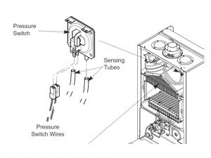
4. Remove all the screws (should be two) that hold top combustion box panel to the pressure switch
3. Replace with the new pressure switch
6. Re-assemble in reverse order of dismantling.
Fan replacement
1. Isolate the appliance
2. Gain General Access. Remove outer case front panel
3. Remember the positions of the sensing tubes (should be two) on the outlet elbow and three wires on the fan motor and
remove them as shown on the picture below
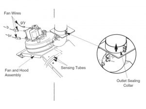
4. Loose the outlet sealing collar screws. Move the collar upwards as much as you can (look at the picture above).
5. Remove all the screws fixing the combustion box (should be four) door. Remove the door.
6. Remove the spring clips retaining the air box side baffle plates. Disengage the tabs on the baffles from the slots in the fan hood.
7. Unscrew all the screws holiding the fan hood to the back panel of the appliance, and draw the fan and hood assembly forwards
8. Remove all the sping washers andthe screws securing the fan to the hood. Move the outlet elbow flue to the new fan
9. Replace with the new fan. Re-use all the spring washers the screws previously removed
10. Re-assemble in reverse order of dismantling
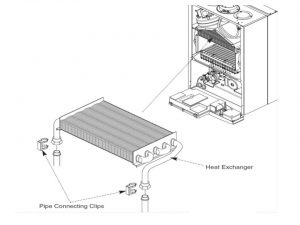
Heat Exchanger replacement
1. Isolate the appliance
2. Gain General Access. Remove outer case front panel
3. Remember the positions of all the sensing tubes (should be two) on the  elbow outlet and all the wires (should be two) on the motor fan. Remove them as shown on the picture below
4. Loose the outlet sealing collar screws. Move the collar upwards as much as you can (look at the picture above)
5. Remove  all the screws(should be four) fixinf the combustion box door. Take off the door
6. Remove the spring clips retaining the air box side baffle plates. Disengage the tabs on the baffles from the slots in the fan hood.
7. Unscrew all the screws holiding the fan hood to the back panel of the appliance, and draw the fan and hood assembly forwards.
8. Drain the primary circuit. Lift the clips connecting pipes (should be two) off the joints in the flow and return pipes.
9. Lift the heat exchanger, disconnect the flow. Return joint pipes. Take it out from the appliance without causing any damage to the rear insulation piece.
10. Put the new heat exchanger in. Pay attention to the tabs on the side insulation carriers. They should involve the slots inside of the side heat exchanger plates.
9. Re-assemble in reverse order of dismantling, re-pressurise the system.
Burner replacementÂ
1. Isolate the appliance
2. Gain General Access. Remove outer case front panel
3. Remove  all the screws(should be four) fixinf the combustion box door. Take off the door
4. Take the burner out of the combustion box. In the lower panel of the combustion box take the electrode grommets off from the slots as shown on the picture below.
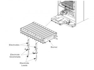
5. Disconnect  all the electrodes grommets and leads from the electrodes. Remove the burner completely.
6. Unscrew the screws securing the electrodes to the burner. Examine the condition of the electrodes, replacing if necessary. Fit the electrodes to the new burner.
7. Involve the brackets of the burner location over the injector manifold studs
8. Re-assemble in reverse order of dismantling.
Injectors replacementÂ
1. Isolate the appliance
2. Gain General Access. Remove outer case front panel
3. Remove the burner as shown on the picture below
4. Unscrew all the screws fixing the inlet elbow to the injector manifold and remove the manifold
5. Unscrew and replace injectors as required and check the sealing gasket. Replace if needed
6. Re-assemble in reverse order of dismantling.
Electrodes replacement
1. Isolate the appliance
2. Gain General Access. Remove outer case front panel
3. Remove  all the screws(should be four) fixinf the combustion box door. Take off the door
4. Draw the burner Take the burner out of the combustion box. In the lower panel of the combustion box take the electrode grommets off from the slots (as demonstrated on the picture in section above).
5. Disconnect the lead and grommet from the electrode being replaced. Unscrew the securing screw and withdraw the electrode to the burner.
6. Re-assemble in reverse order of dismantling.
Insulation replacement
1. Isolate the appliance
2. Gain General Access. Remove outer case front panel
3. Remove  all the screws(should be four) fixinf the combustion box door. Take off the door
4. Move the side insulation pieces away from its carriers.
5. Remove the heat exchanger as described on the picture below and slide out the side pieces.
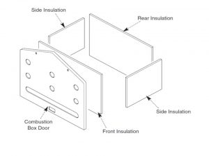
6. Replace the combustion door box insulation by bending up all the retaining tabs (should be two).
7. Re-assemble in reverse order of dismantling.
Gas Valve replacement
1. Isolate the appliance
2. Gain General Access. Remove outer case front panel
3. Unscrew the nut on the gas feed pipe under the boiler.
4. Completely unscrew the securing screws and hinge the facia panel down.
5. Disconnect the earth wire and pressure sensing pipe from the valve. Unscrew all the screws fixing valve to the electrical plug. Disconnect the plug. Disconnect the wires from the valve modulator as shown on the picture below
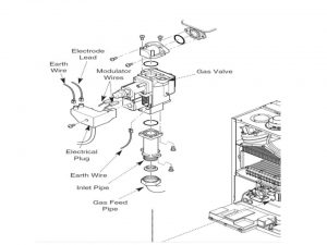
6. Pull the earth wire off the spade terminal on the valve.
7. Remove all the screws fixing the bottom boiler bottom panel to the inlet pipe flange and those securing the burner manifold to the outlet manifold
7. Remove the valve from the boiler
8. Note the orientation of the inlet pipe and outlet manifold. Unscrew the fixing screws and remove the manifold and the pipe.
9. Veryfy if the ‘O’ ring seals  are not damaged, replace when needed
10. Put the pipe inlet and manifold outlet to the new valve, All ‘O’ ring seals must be in the right place
11. Re-assemble in reverse order of dismantling, verify burner pressure.
Temperature Sensor replacement
1. Isolate the appliance
2. Gain General Access. Remove outer case front panel
3. Ease the retaining tab on the sensor away and disconnect the electrical plug. as shown on the picture below
4. Unscrew the sensor from it’s pocket
5. Re-assemble in reverse order. The plug will only fit one way.
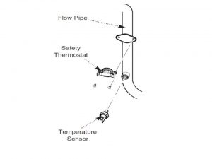
Safety Thermostat replacement
1. Isolate the appliance
2. Gain General Access. Remove outer case front panel
3. Pull the two electrical connections off the thermostat as shown on the picture in the section above
4. Remove the screws securing the thermostat to the mounting plate on the flow pipe
5. Re-assemble in reverse order
Pump replacement – Head Only
1. Isolate the appliance
2. Gain General Access. Remove outer case front panel
3. Drain the primary circuit and remove the socket head screws securing the pump head to the body and draw the head away as shown the picture below
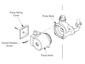
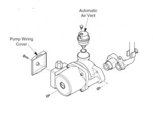
4. Unscrew the screw on the pump wiring cover and remove the cover by using flat-bladed screw driver. Push the cable fixing levers downwards. Release each wire- pay attention to each cable position.
5. A standard Grundfos 15-50 replacement head can now be fitted. Connect the wiring to the new head. The pump speed must be set to 3.
4. Re-assemble in reverse order of dismantling.
Pump replacement – CompleteÂ
1. Isolate the appliance
2. Gain General Access. Remove outer case front panel
3. Drain the primary circuit and unscrew the automatic air vent from the pump body. Unscrew the two screws securing the body to the pipe and manifold and draw the pump forwards.
4. Unscrew the screw on the pump wiring cover and remove the cover. Unscrew the screw on the pump wiring cover and remove the cover by using flat-bladed screw driver. Push the cable fixing levers downwards. Release each wire- pay attention to each cable position.
5. Connect the wiring to the new pump. Examine the ‘O’ ring seals on the return pipe and manifold, replacing if necessary.
6. Fit the air vent to the pump body
7. Re-assemble in reverse order of dismantling.
Automatic Air Vent replacementÂ
1. Isolate the appliance
2. Gain General Access. Remove outer case front panel
3. Drain the primary circuit and unscrew the automatic air vent from the pump body as shown on the picture below
4. Examine the ‘O’ ring seal, replacing if necessary, and fit it to the new automatic air vent.
5. Re-assemble in reverse order of dismantling.
Pressure Gauge replacement
1. Isolate the appliance
2. Gain General Access. Remove outer case front panel
3. Drain the primary circuit and unscrew the nut on the pressure gauge capillary as shown on the picture below
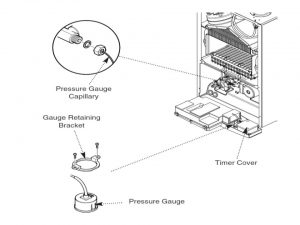
2. Remove the timer cover and release to the side the timer wiring. Unscrew the screws fixing the retaining bracket gauge
3. Remove the gauge assembly and bracket. Remove left bracket
4. Re-assemble in reverse order of dismantling
Expansion Vessel replacement
1. Isolate the appliance
2. Gain General Access- to replace the expansion vessel it is necessary to remove the boiler from the wall. Remove outer case front panel
Attention! Alternatively a vessel of equivalent capacity can be fitted on the system return pipe as close as possible to the boiler
3. Drain the system and unscrew all gas and water connections. The elbow flue should be removed
4. Unscrew the nut preset on the putlet spigot of the vessel. Remove the spring washer and the locknut fixing the spigot to the boiler chassis as shown on the picture below
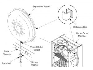
5. Unscrew the screws and remove the appliance upper cross member. Slide the expansion vessel out of the retaining clips
6. Re-assemble in reverse order of dismantling. Fully recommission the appliance and system.
Gas Valve Plug/Spark Generator replacement
1. Isolate the appliance
2. Gain General Access. Remove outer case front panel
3. The valve electrical plug, spark generator and lead are combined in one unit
4. Disconnect the earth wire and electrode lead from the plug/generator. Unscrew the screw securing the plug/generator to the valve and disconnect
5. The control box screws should be removed and the cover retaining barbs should be released from their slots. Disengage the rear tabs of the cover from the control box hinge pin
6. Remove the plug lead from the cable clip and disconnect the multi-pin plug from the PCB
7. Reassemble in reverse order of dismantling.
Pressure Relief Valve replacement
1. Isolate the appliance
2. Gain General Access. Remove outer case front panel
3. Drain the primary circuit.
4. Disconnect the discharge pipe from the valve. Use the hexagon key to release the valve as shown on the picture below
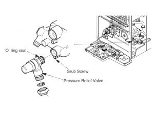
5. Note the orientation of the valve, rotate it and withdraw it from the manifold
6. Replace with the new valve and ‘O’ ring seal and set to the previously noted orientation.
7. Re-assemble in reverse order of dismantling
P.C.B. replacement
1. Isolate the appliance
2. Gain General Access. Remove outer case front panel
3. Note the settings of the temperature control knobs. Move the knobs anticlockwise and pull them off from the drive pins
4. The control box screws should be removed and the cover retaining barbs should be released from their slots. Disengage the rear of the cover from the control box hinge pin as shown on the picture below
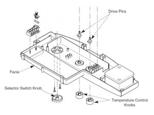
5. Note the position of all plugs and wires on the P.C.B. and disconnect them. Pull the drive pins off the P.C.B.
6. Unscrew the securing screws and remove the P.C.B.
7. Re-assemble in reverse order of dismantling. Make sure that the temperature controllers are reset to their previous positions
Attention! Move the the selector switch anti-clockwise till you reach the reset position and hold for at least 5 seconds to reset the boiler.
Selector Switch replacement
1. Isolate the appliance
2. Gain General Access. Remove outer case front panel
3. Note the setting of the selector switch knob
4. The control box screws should be removed and the cover retaining barbs should be released from their slots. Disengage the rear of the cover from the control box hinge pin as shown on the picture in the section above.
5. Note the position of the electrical connections and the orientation of the switch. Remove the electrical connections.
6. Remove the screws securing the switch to the facia panel
7. Replacew with the new switch, ensuring that it is correctly positioned
8 Re-assemble in reverse order of dismantling.
Plate Heat Exchanger replacement
1. Isolate the appliance
2. Gain General Access. Remove outer case front panel
3. Drain the primary circuit.
4. While supporting the heat exchanger unscrew the screws securing it to the brass manifolds.
5. Withdraw the heat exchanger upwards and to the left of the gas valve, take care not to damage any wires or controls as shown on the picture below
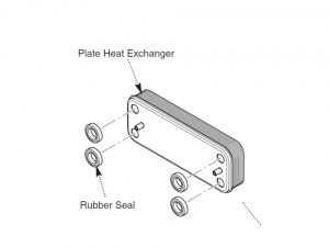
6. There are four rubber seals between the manifolds and heat exchanger which may need replacement.
7. Ease the seals out of the manifold. Replace carefully, ensuring that when the seal is inserted into the manifold it is parallel and pushed fully in.
8. When fitting the new heat exchanger note that the left hand location stud is offset towards the centre more than the right hand one.
7. Re-assemble in reverse order of dismantling.
Diverter Valve Assembly
The diverter valve assembly comprises of a central heating pressure differential valve and a domestic hot water pressure differential valve. These are connected to a manifold which is joined to the plate heat exchanger.
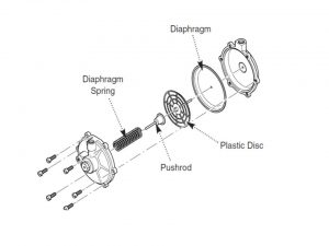
DHW Pressure Differential Valve replacement
1. Isolate the appliance
2. Gain General Access. Remove outer case front panel
3. Drain the primary circuit.
4. Unscrew the screw securing the microswitch bracket to the valve as shown on the picture below
5. Disconnect the two sensing pipes and slacken the grub screws securing the valve to the diverter manifold.
6. Draw the valve away from the diverter manifold. The valve may now be replaced or split to examine the diaphragm.
7. To examine the diaphragm hold the valve body securely and carefully remove the six screws. The diaphragm spring will force apart the two halves of the valve.
8. Remove the plastic disc and pushrod assembly. Carefully examine the diaphragm and replace it if damaged
9. Re-assemble in reverse order of dismantling.
CH Pressure Microswitch replacement
1. Isolate the appliance
2. Gain General Access. Remove outer case front panel
3. Remove the two wires from the pressure microswitch.
4. Unscrew the screw securing the microswitch bracket to the valve body.
5. Reassemble in reverse order of dismantling.
Flow Regulator replacementÂ
1. Isolate the appliance
2. Gain General Access. Remove outer case front panel
3. Unscrew the filter cartridge from the inlet/return manifold as shown on the picture below
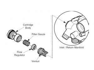
4. Unscrew the venturi and remove the flow regulator.
5. Check the cleanliness of the filter gauze, rinsing thoroughly in clean water as necessary. Replace with the new flow regulator
6. Re-assemble in reverse order of dismantling.